Chapter 10: Unified Modeling Language (UML)
UML enable us to model computer applications. It is used for visualizing, specifying, constructing and documenting the components of a software system.
UML notations are used for modeling in UML. So let us learn about the UML notations. UML notations are building blocks of UML diagrams.
| S.N. | UML Notation Name | Notation Type | Notation Diagram | Description |
|---|---|---|---|---|
| 1 | Class | Structural Notation |  |
Represents group of object with similar properties and methods. In this picture Car is class with two properties and four methods |
| 2 | Component | Structural Notation |  |
Describes physical part of a system. In this picture, Phone is physical component of a telephone network. |
| 3 | Interface | Structural Notation |  |
An interface is a shared boundary across which two or more separate components of a system exchange information. In this picture Person is name of the interface |
| 4 | Node | Structural Notation |  |
Node is a computational resource upon which UML artifacts may be deployed for execution There are two types of nodes. 1. A device represents hardware devices. 2. An execution environment represents software containers. In this picture Desktop is a node name. Web browser is an execution environment component. |
| 5 | Use Case Action/Event | Structural Notation | 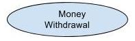 |
A use case is a list of actions or event steps defining the interactions between a role (actor) and a system to achieve a goal. In this picture Money Withdrawal is an action in ATM use case |
| 6 | Association | Relationship Notation | |
Association is a relationship between classes which is used to show how instances of classes can be linked to each other. This picture represents association between author and book. One book can be written by one or more authors and one author can write one or more books. |
| 7 | Dependency | Relationship Notation | |
Represents relationship between two elements. In this picture, A is dependent on B |
| 8 | Generalization | Relationship Notation |  |
Generalization is a relationship between super class (parent class, base class) and subclass (child class). Generalization is also called as the process of extracting shared characteristics from two or more classes, and combining them into a generalized super class. |
| 9 | Realization | Relationship Notation |  |
In realization two elements are connected. One defines responsibility and other implements the responsibility. Realization is a specialized relationship between two sets of model elements, one representing a specification (supplier) and the other represents an implementation (client). In this picture responsibility is defined by interface A and implemented by class B. |
| 10 | Navigation | Navigability Notation | |
Navigation is movement from one element to other. This picture indicates navigation from A to B . |
| 11 | Interaction | Activity/Behavior Notation |  |
Interaction represents the exchange of message between the elements (Lifeline). This picture represents the exchange of the message between A and B. |
| 12 | State | Activity/Behavior Notation |  |
State represents behavior of an object at given point of time in response to an event or action. In the picture start is a state of an object. |
| 13 | Package | Grouping Notation |  |
A package is a grouping element. A package in UML is used group the elements together and provide namespace for the grouped elements. In the picture Business Components represents a package. |
| 14 | Note | Annotation Notation |  |
Annotations are used to provide description or comment. Description & comments can be written inside the annotation box. |
Classification of UML Diagrams
UML diagrams can be classified into 3 categories
- Structure Diagrams
- Behavior Diagrams
- Interaction Diagrams
Structure Diagrams
Structure diagrams document how different structures make up a system (example: Application, Database etc). It shows structure of different components/modules of the system and how they connect and interact with each other.
Following are the types of Structure Diagrams.
- Class Diagram
- Object Diagram
- Component Diagram
- Package Diagram
- Deployment Diagram
Behavior Diagrams
UML Behavioral diagrams are used to show the functionality of the system. They help in specifying and visualizing the dynamic aspects of the system.
Following are the types of Behavior Diagrams.
- Use Case Diagram
- Activity Diagram
- State Machine Diagram
Interaction Diagrams
Interaction diagram is also called sequence diagram. It shows how group of objects collaborate in a use case. It illustrates how objects interact via messages. Interaction diagrams model the behavior of use cases by describing the way groups of objects interact to complete the task.
Following are the types of Interaction Diagrams.
- Sequence Diagram
- Communication Diagram
- Timing Diagram
- Interaction Overview Diagram

